# S-132 Bill of Materials (Draft)
TIP
To see the images in full size you can right-click on an image and Open Image in New Tab
Notes on the PCB
- PCBs are production (V1.5.1)
- Part identifiers are correct and there are no known errors
# Main S-132 PCB (green)
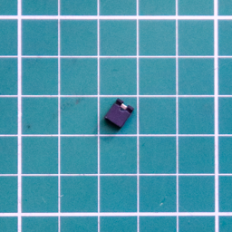
# Surface Mount Device (SMD) components
Don't Panic
- Yes there are four SMD components!
- You can do it!
- You can do it with a regular soldering iron, but you are going to need flux
| Part | Quantity | PCB | Description |
|---|---|---|---|
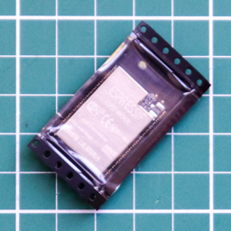 | 1 | ESP32-WROVER U1 | ESP-32 WROVER Module |
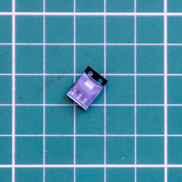 | 1 | NCP1117-33 U2 | NCP1117-33 LDO Linear Regulator |
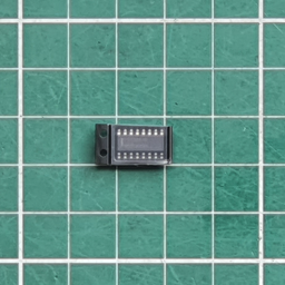 | 1 | 74CBTLV3257 U3 | 74CBTLV3257 SOIC-16 Quad 1-of-2 Multiplexer/Demultiplexer |
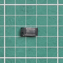 | 1 | 74HC00 U4 | 74HC00 SOIC-14 Quad NAND Gate |
# Through Hole (THT) components
| Part | Quantity | PCB | Description |
|---|---|---|---|
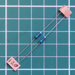 | 2 | R1, R2 | 120 Ohm Resistor [Brown, Red, Black, Black, Brown]Only required if using the PS/2 keyboard |
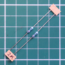 | 2 | R3, R4 | 2K Ohm Resistor [Red, Black, Black, Brown, Brown]Only required if using the PS/2 keyboard |
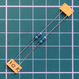 | 1 | R5, R13 | 10K Ohm Resistor [Brown, Black, Black, Red, Brown] |
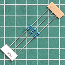 | 3 | R6, R8, R10 | 806 Ohm Resistor [Grey, Black, Blue, Black, Brown] |
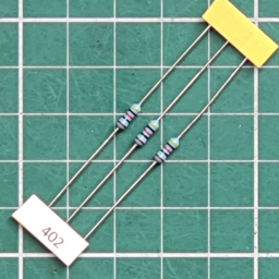 | 3 | R7, R9, R11 | 402 Ohm Resistor [Yellow, Black, Red, Black, Brown.] |
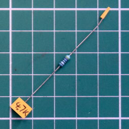 | 1 | R12 | 4.7K Ohm Resistor [Yellow, Violet, Black, Brown, Brown] |
 | 1 | R14 | 121 Ohm Resistor [Brown, Red, Brown, Black, Brown] |
 | 1 | R15 | 243 Ohm Resistor [Red, Yellow, Orange, Black, Brown] |
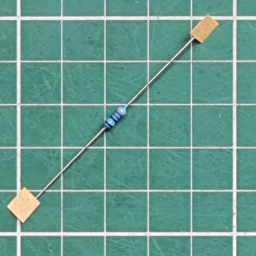 | 1 | R16 | 487 Ohm Resistor [Yellow, Gray, Violet, Black, Brown] |
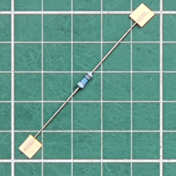 | 1 | R17 | 976 Ohm Resistor [White, Violet, Blue, Black, Brown.] |
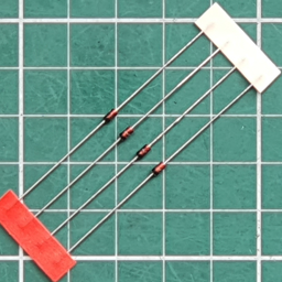 | 4 | D1, D2, D3, D4 | 1N4148 Signal DiodeDiodes have polarity, ie. they must be inserted the correct way around to function properly. |
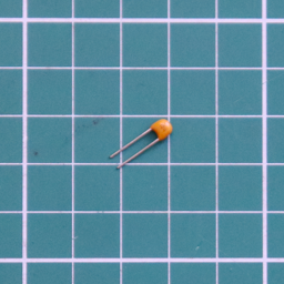 | 1 | C2 | 1 uF MLC (105) Capacitor |
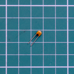 | 7 | C1, C6, C7, C8, C9, C10, C11 | 100 nF (104) MLC Capacitor |
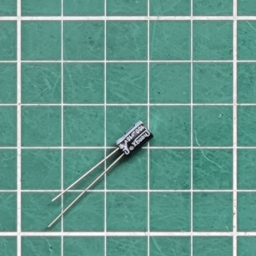 | 2 | C3, C12 | 100 uF Electrolytic CapacitorElectrolytic capacitors have polarity, ie. they must be inserted the correct way around to function properly. +VE to the Square Pad |
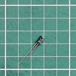 | 1 | C4 | 22 uF Electrolytic CapacitorElectrolytic capacitors have polarity, ie. they must be inserted the correct way around to function properly. +VE to the Square Pad |
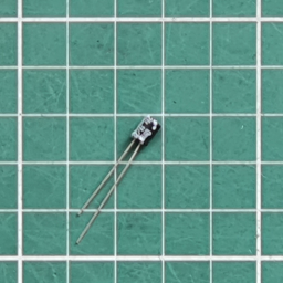 | 2 | C5, C13 | 10 uF Electrolytic CapacitorElectrolytic capacitors have polarity, ie. they must be inserted the correct way around to function properly. +VE to the Square Pad |
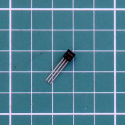 | 1 | Q1 | S8050 NPN Transistor TO-92 |
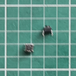 | 2 | Prog, Reset | Tactile Push Button Switch SPST |
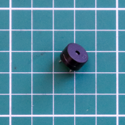 | 1 | Bell | Buzzer 12.2mm dia.The Buzzer is polarized, ie. it must be inserted the correct way around to function. +VE to the Square Pad |
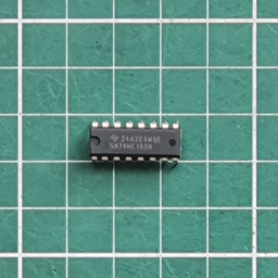 | 1 | U5 | 74HC165Shift Register 8-bit, parallel load |
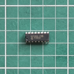 | 1 | U6 | MCP30088 Channel 10-bit Analog-to-Digital Converter (ADC) |
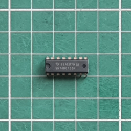 | 1 | U7 | 74HC1383-to-8 line Decoder/Demultiplexer, inverting |
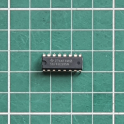 | 1 | U8 | 74HC5958-bit serial in/out Shift Register 3-State Outputs |
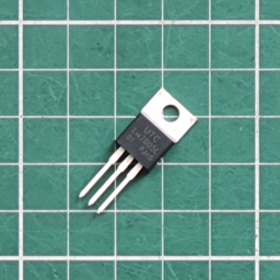 | 1 | LM7805 U9 | LM7805 +5V DC Linear Regulator |
# Through Hole (THT) headers
| Part | Quantity | PCB | Description |
|---|---|---|---|
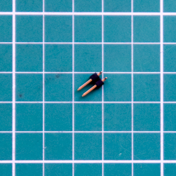 | 1 | JP1 5V Pwr | 2 Pin Header - Horizontal |
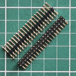
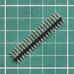 | 1 | FTDI Program | 6 Pin Header - VerticalCut from 20 Pin male header |
| 1 | Keyboard | 6 Pin Header - VerticalCut from 20 Pin male header.Only required if using the USB-HID keyboard |
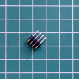 | 1 | Patch | 8 Pin Header (4x2)- VerticalSee notes for use of this header |
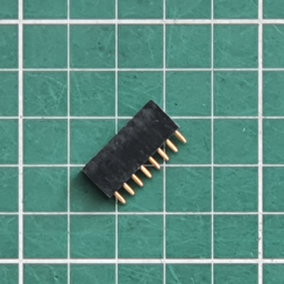 | 1 | S-132 | 16 Pin Header (8x2)- Female, VerticalFit to the underside of the PCB - attaches to the IMSAI8080/Cromemco Z-1 |
| 1 | KB Reset | 2 Pin Header - VerticalCut from 20 Pin male header.Only required if using the USB-HID keyboard |
 | 4 | For JP1 & Patch as required | Header Pin Shunts |
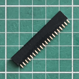 | 1 | D+7AIO | Connector 20x2 FemaleSits between the DIP-16 IC sockets. This connector forms a 40-pin socket for the D+7AIO |
# Through Hole (THT) connectors
| Part | Quantity | PCB | Description |
|---|---|---|---|
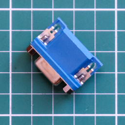 | 1 | VGA | DB15 VGA Female Socket - Right Angled |
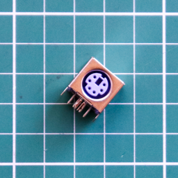 | 1 | PS/2 | Mini-DIN-6 PS/2 Keyboard Female Socket - Right AngledOnly required if using the PS/2 keyboard |
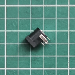 | 1 | Power | 6.2mm DC Barrel Jack Connector |
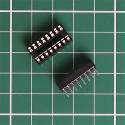 | 4 | (U4, U6, U7, U8) | 16 pin DIP SocketOne for each IC - U4, U6, U7, U8 |
# Printed Circuit Board (PCB)
| Part | Quantity | Description |
|---|---|---|
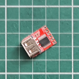 | 1 | USB-HID Keyboard InterfaceIf ordered |
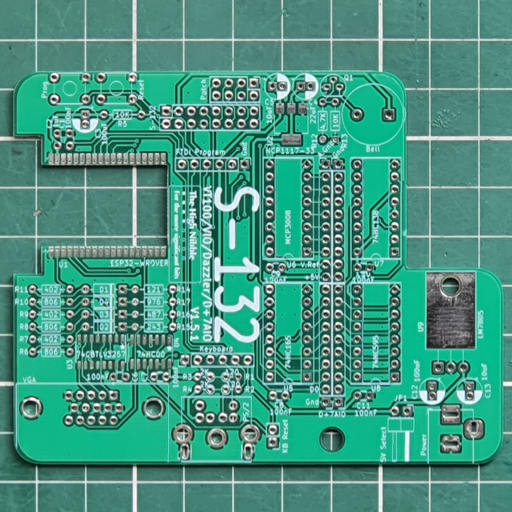 | 1 | Front view |
# Mounting hardware
| Part | Quantity | Description |
|---|---|---|
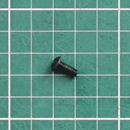 | 1 | M4x10mm Hex Socket ScrewThe M4 socket screw is used to fix the S-132 to the clear acrylic back of the IMSAI80080/Cromemco Z-1. You will need to tap or drill a hole to secure the M4 socket screw. |
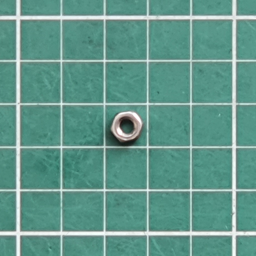 | 1 | M4 Hex Nut NylonThe nut can be used as a spacer between the S-132 PCB and the acrylic back of the IMSAI80080/Cromemco Z-1 |
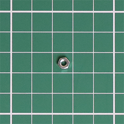
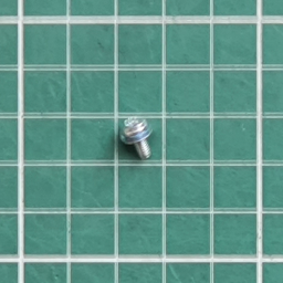 | 1 | M3x5mm Zinc Machine Screw & WasherThe M3 machine screw, washer and nut are used to secure the LM7805 to the S-132 PCB, to aide thermal conduction with the PCB. |
 | 1 |
# Joystick Adapter (yellow)
| Part | Quantity | PCB | Description |
|---|---|---|---|
 | 1 | Pin 1 | 40 Pin Header (20x2)- HorizontalFit to underside of PCB. |
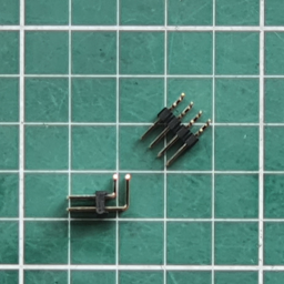 | 2 | Pad 1, Pad 2 | 8 Pin Header (4x2)- HorizontalFit to top of PCB. |
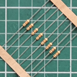 | 8 | R100 - 107 | 10K Ohm Resistor [Brown, Black, Orange, Gold] |
| 1 | A.Gnd | 2 Pin Header - VerticalCut from 20 Pin male header |
| 1 | Ref.Voltage | 3 Pin Header - VerticalCut from 20 Pin male header |
| 1 | Audio Patch | 3 Pin Header - VerticalCut from 20 Pin male header |
| 1 | Amp | 3 Pin Header - VerticalCut from 20 Pin male header |
| 4 | For A.Gnd, Ref.Voltage & Audio Patch as required | Header Pin ShuntsFit a shunt to both A.Gnd and the +5V & Center pins of Ref.Voltage |
| NOT SUPPLIED NOT REQUIRED | 1 | C100 | 100 nF (104) MLC Capacitor |
| NOT SUPPLIED NOT REQUIRED | 1 | C101 | 1 uF (105) MLC Capacitor |
| NOT SUPPLIED NOT REQUIRED | 1 | MCP1541 | MCP1541 4.096V Voltage Reference |
| Part | Quantity | Description |
|---|---|---|
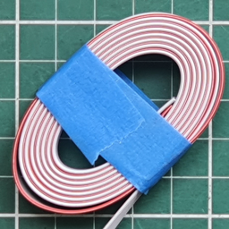 | 2 x 36 inch | 8-core IDC Ribbon CableConnects JS-1 Joysticks to the Joystick Adapter |
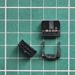 | 4 | 8-pin IDC Ribbon Cable Header - FemaleConnects JS-1 Joysticks to the Joystick Adapter |
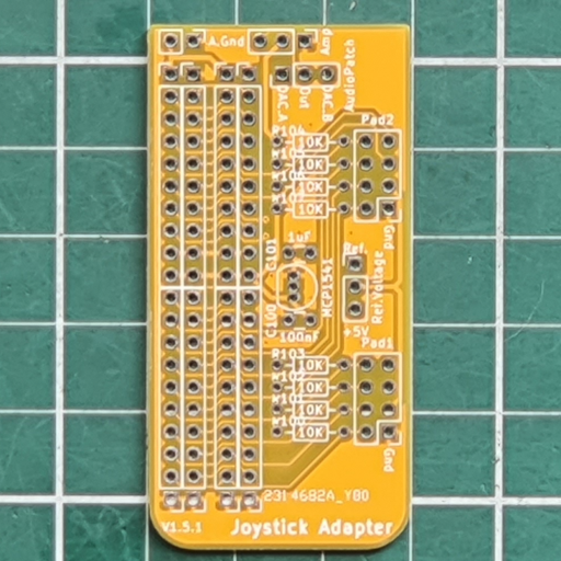 | 1 | Front view |
# JS-1 Analog Joystick (yellow x 2)
| Part | Quantity | PCB | Description |
|---|---|---|---|
| 4 each | SW1 - 4 | Tactile Push Button Switch SPST |
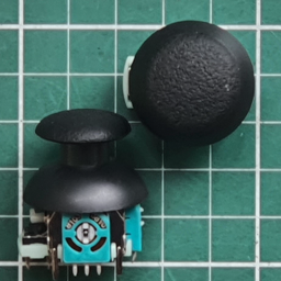 | 1 each | 2-axis Analog Joystick - 10Kohm | |
| 1 each | 8 Pin Header (4x2)- HorizontalFit to top of PCB. |
| Part | Quantity | Description |
|---|---|---|
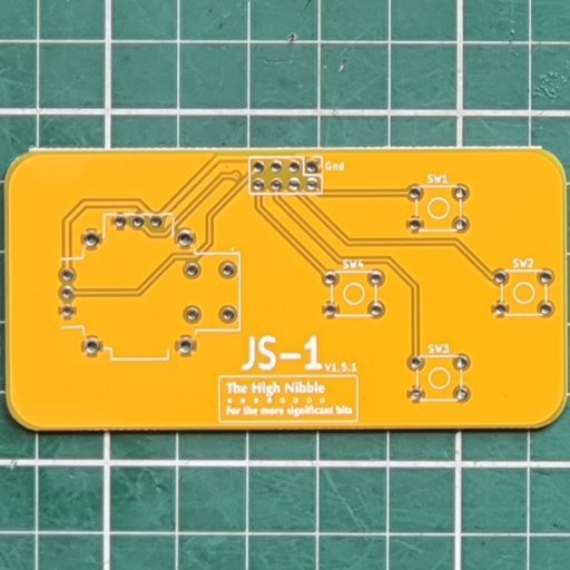 | 2 | Front view |
# Parallel Printer (red)
| Part | Quantity | PCB | Description |
|---|---|---|---|
| 1 | Pin 1 | 40 Pin Header (20x2)- HorizontalFit to underside of PCB. |
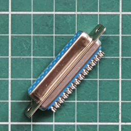 | 1 | Printer | DB25 Female Socket - Solder lug |
| Part | Quantity | Description |
|---|---|---|
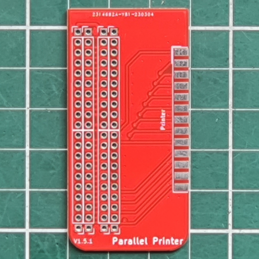 | 1* | Front view |
# Prototype Adapter (green)
| Part | Quantity | PCB | Description |
|---|---|---|---|
| 1 | Pin 1 | 40 Pin Header (20x2)- HorizontalFit to underside of PCB. |
| Part | Quantity | Description |
|---|---|---|
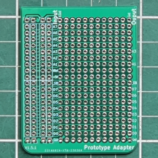 | 1* | Front view |