# Configuration - v1.10.0 or later
TIP
As of October 2022 kits ship with firmware v1.10.0 or later.
The following configuration guide relates to these firmware versions.
If you are still running and older firmware revision v1.9.1 or earlier, the previous version of the Configuration Guide is available here
# Overview
WARNING
Just like the real IMSAI 8080 computer, the default configuration of your kit is an empty machine. While you can enter instructions using the toggle switches (and you should experiment with this sometime) it's more interesting to run some real software. The default configuration is like an empty machine with no ROM only RAM.
In order to run any applications, you will need to activate a virtual ROM (eg. to run BASIC, or boot a floppy disk) and maybe load an operating system (such as CP/M) from a virtual disk.
Also like the original computer, your IMSAI 8080esp has no video output port. Owners of the original IMSAI 8080 would connect a serial terminal (either a teletype printer or visual display unit) to a serial port. While you can still do this (see Serial Communications section), this modern kit offers a much easier solution using Wi-Fi.
Once power is applied to your kit, the ESP32 will create a Wi-Fi Access Point. You can connect your computer to this Wi-Fi network as if it were connected to a Wi-FI router. You can then open a web page, the Desktop UI, that will give you full access to the IMSAI 8080esp - including a virtual serial terminal (TTY:), floppy disks, printer (LPT:) and more.
Once connected, you can then configure the IMSAI 8080esp to connect directly to your home Wi-Fi, so you can use it without having to change your Wi-FI settings again.
# Getting connected
- Plug in the power to the IMSAI 8080esp kit.
- On your computer, open the Wi-Fi settings and select the
imsai8080network (SSID). - When prompted for a password, enter
password.
Your computer should now be connected, and you will be able to open the Desktop UI. The web interface has been written and tested with the Chrome browser in mind, and you might find it works differently if you are using a different browser.
- If you have a Mac, open your browser and enter
imsai8080orimsai8080.localas the web address. - If you have a PC, open your browser and enter
imsai8080or192.168.4.1as the address.
# Default configuration
# IMSAI 8080 (guest)
WARNING
The default configuration is like an empty machine with no ROM only RAM.
- RAM is 64K occupying the entire address space from
0000htoFFFFh - CPU is Intel 8080 @ 2MHz with support for undocumented op-codes
- No boot ROM is active by default
# ESP32 (host)
- Wi-Fi set to Access-Point (AP) mode with the default SSID of
imsai8080, password ofpassword - Hostname (HOSTNAME environment variable) set to
imsai8080(imsai8080.localfor mDNS) - Port (PORT environment variable) set to
80 - Timezone (TZ environment variable) set for AEST+10, ADST+11 (ie. Sydney, Australia)
- Time server (NTP_SERVER environment variable) set to
pool.ntp.org - POST (Power On Self Test) disabled
- Console log level set to
NONE(details to follow)
TIP
Once you are connected to the Wi-Fi network, start a Chrome browser and enter the URL http://imsai8080 to see the Desktop UI.
# Startup configuration (Non-Volatile Storage, NVS)
The startup configuration is modified via the toggle switches on the front panel.
To enter startup configuration mode, follow the sequence:
- ensure the ESP32 is connected to a USB power source, the red LED on the ESP32 board should be illuminated
- turn the front panel power switch off,
PWR OFF, the down position - hold the
EXAMINEtoggle in the Examine, up position - press and release the
Resetswitch while holding theEXAMINEtoggle up - hold the
EXAMINEtoggle for a second or two - release the
EXAMINEtoggle
TIP
There are 2 Reset switches available that both do the same thing:
- The
Tactile Switch SPST-NOyou installed in theResetposition on the PCB - The small tactile switch on the ESP32 board marked
EN - NOT the blue toggle switch on the front panel
The IMSAI 8080esp should now be in startup configuration mode. This is indicted by a running LED pattern (right to left) on the 4 LEDS at the right hand side of the front panel (HOLD, WAIT, RUN, INTERRUPTS ENABLED).
TIP
The current startup configuration value is displayed on the Address Bus LEDs (bits 0-15) when you enter startup configuration mode.
TIP
The whole procedure, including entering a value to boot into CP/M 2.2 (see below) is demonstrated in this Kit Assembly video
WARNING
When you Deposit a new startup configuration value, all the bits of the current value are overwritten. If your objective is to modify the existing value changing only a few of the bits, you must toggle in all the bits of the existing value indicated by the Address Bus LEDs and then switch the bits you want to configure differently, before you Deposit this new value.
Booting into XYBASIC
To configure the IMSAI 8080esp to boot directly into a ROM based XYBASIC in Z80 mode @ 4 MHz, the following startup configuration value can be used.
- Binary: 0000 0100 0101 0000
- Octal: 002120
- Hexadecimal: 0450
- Enter startup configuration mode (above)
- Toggle in this value on the Address toggle switches
- Raise the
DEPOSITtoggle to the Deposit, up position to store the entered startup configuration value. - Reboot the IMSAI 8080esp by pressing a
Resetswitch
Booting into CP/M 2.2
To configure the IMSAI 8080esp to boot from the disk image in drive DSK:A: in Z80 mode @ 4 MHz, the following startup configuration value can be used. You can mount the cpm_22.dsk disk image in drive DSK:A: via the Desktop UI.
- Binary: 0000 1001 0101 0000
- Octal: 004520
- Hexadecimal: 0950
- Enter startup configuration mode (above)
- Toggle in this value on the Address toggle switches
- Raise the
DEPOSITtoggle to the Deposit, up position to store the entered startup configuration value. - Reboot the IMSAI 8080esp by pressing a
Resetswitch
| Address Bit | Name | Equivalent Flag | Description |
|---|---|---|---|
| 0 | NVS_POST | n/a | Enable Power On Self Test (POST) |
| 1-2 | NVS_LOG_LEVEL | n/a | Set ESP32 console Log Level, 0 = NONE; 1 = ERROR; 2 = WARN; 3 = INFO |
| 3 | NVS_IF_STA | n/a | Set Wi-Fi Mode, 0 = Access Point Mode (AP); 1 = Station Mode (STA) |
| 4 | NVS_Z80 | -z, -8 | Enable Z80 CPU emulation, 0 = 8080 -8; 1 = Z80 -z |
| 5 | NVS_NO_UNDOC | -u | Suppress support for undocumented op. codes, 1 = -u |
| 6 | NVS_4MHZ | -f | Set CPU speed, 0 = 2 MHz -f 2; 1 = 4 MHz -f 4 |
| 7 | NVS_UNLIMITED | -f 0 | Set CPU speed to Unlimited, 0 = use speed from bit 6; 1 = Unlimited -f 0 |
| 8-10 | NVS_MEMORY_MAP | -M | Set memory map, 0 = default 64K RAM, 1-7 = use memory map n -M n |
| 11 | NVS_BANK_ROM | -R | Enable MPU-B(A) style Banked ROM/RAM functionality, 1 = -r. Only compatible with MPU-A ROM images. |
| 12-14 | Reserved for future use | ||
| 15 | NVS_AUTO_RUN | Autorun - The CPU will automatically run when the machine is switched on (PWR ON) |
To set the startup configuration mode value, follow the sequence:
- To set a bit, put the corresponding Address toggle switch in the up position.
- To clear a bit, put the corresponding Address toggle switch in the down position.
- Raise the
DEPOSITtoggle to the Deposit, up position to store the entered startup configuration value.
WARNING
The IMSAI 8080esp must be rebooted for the new configuration to take effect.
This can be done by raising the RESET toggle or by pressing a Reset switch.
TIP
For further details about the Equivalent Flag refer to the Z80PACK documentation for the imsaisim machine.
# Serial Communications (RS232, USB)
The IMSAI 8080esp is configured with two virtual IMSAI SIO-2 UART boards.
Each SIO board provides two serial I/O ports. The board/port/devices are assigned as follows:
| SIO Board | UART Port | I/O ports (decimal) | Connected Device | CP/M 2.2 Device via BIOS |
|---|---|---|---|---|
| #1 | A (SIO1) | 2 (data), 3 (status) | Physical UART0 (Tx/Rx Patch pins & USB) | TTY: |
| B | 4 (data), 5 (status) | Virtual VIO keyboard | CRT: (input only, no output) | |
| #2 | A (SIO2) | 34 (data), 35 (status) | Physical UART1 (IO22/IO5 Patch pins) | UC1: (default) |
| B | 36 (data), 37 (status) | Virtual 'AT' Hayes modem | (assignable as UC1:) |
When the machine boots, the virtual SIO1 UART (board #1 port A) is routed to the physical UART0 on the ESP32-PICO-KIT.
- This enables you to use any software on the IMSAI 8080 that communicates via this UART on the SIO (namely the CP/M TTY: as console) using a terminal or terminal emulator depending your method of connection.
- The default speed with the current firmware is 115200 baud @ 8N1
TIP
Both the ESP32 console log and the IMSAI 8080 SIO1 (TTY:) will be directed to the serial UART0. If you set the NVS_LOG_LEVEL to INFO (3) this will likely send console log messages during normal use of the machine. It is recommended to set the NVS_LOG_LEVEL to a lower level during normal operation.
WARNING
Behavior of serial communications is further effected by the settings on the virtual SIO UARTs (SIO1 and SIO2). See SIO flags in the system.conf file below, for further details.
WARNING
If you start the Desktop UI from a web browser and the TTY: virtual device is connected (default behavior) then the virtual* SIO1 UART (TTY:) is disconnected from the physical UART0 on the ESP32-PICO-KIT and instead re-routed to the TTY: virtual device on the Desktop UI. If the TTY: virtual device is disconnected, then the SIO1 UART is re-routed back to the UART0 on the ESP32-PICO-KIT, ie. only one of these two destinations can be connected at a time.
Note: the ESP32 console log is always sent to the physical UART0 and is never redirected.
# Serial UART over USB
The ESP32-PICO-KIT supports serial communications from UART0 over USB. It uses a Silicon Labs CP210x USB to UART bridge
- connect the
ESPP32-PICO-KITto a PC using a suitable USB cable - start a terminal emulator on the PC set for 115200 baud 8N1 connected to the serial device your OS identifies the
ESP32-PICO-KITon- Windows will be a COMx: port
- OSX will be /dev/tty.SLAB_USBtoUART
- Linux will be /dev/ttyUSB0 (or similar, TBA)
TIP
If you do not see a TTY/COM port on your PC presented by the ESP32-PICO-KIT when connected, you may need to install a driver for the Silicon Labs CP210x USB to UART bridge.
Drivers are available direct from the manufacturer at https://www.silabs.com/products/development-tools/software/usb-to-uart-bridge-vcp-drivers
Additional information is available from the Espressif (manufacturer of the ESP32-PICO-KIT) web site at https://docs.espressif.com/projects/esp-idf/en/latest/get-started/establish-serial-connection.html
# Serial UART over RS232
WARNING
Serial UART0 over RS232 and Serial UART0 over USB are mutually exclusive, ie. they cannot be used at the same time.
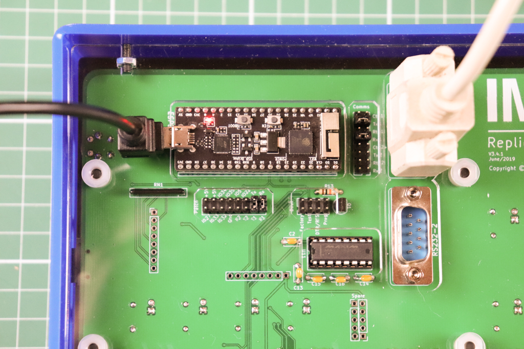
Serial UART over RS232 is configured by using the supplied jumpers/shunts to bridge the required pins on the Patch and Comms headers accessible on the rear of the PCB, and connecting a suitable RS232 device to one of the DE-9M connectors labeled RS232-1 and RS232-2
RS232 line levels are provided by the Maxim MAX3232 IC see the data sheet for details.
You must position 4 of the jumpers/shunts provided to enable a Serial UART over RS232. This image shows the currently supported configuration for the jumpers/shunts on both the Patch and Comms headers for UART0 to RS232-1
# UART0 to RS232-1
# Patch header
- bridge Tx - T1 - vertical position second from right
- bridge Rx - R1 - vertical right most position
# Comms header
- bridge @ Tx1 - horizontal second position from top
- bridge @ Rx1 - horizontal fourth position from top
# UART1 to RS232-2
# Patch header
- bridge IO22 - T2 - vertical position third from right
- bridge IO5 - R2 - vertical position fourth from right
# Comms header
- bridge @ Tx2 - horizontal third position from bottom
- bridge @ Rx2 - horizontal last position at bottom
# Configuring physical UART parameters (speed, data & stop bits)
You can configure the parameters for both UART0 (RS232-1/USB) and UART1 (RS232-2) via the boot.conf file.
See UART Configuration in the boot.conf file below, for further details.
# Wi-Fi Communications
The ESP32 has on-board Wi-Fi and can boot in either Access Point (AP) or Station (STA) mode. The mode is determined by the NVS_IF_STA bit in the startup configuration stored in NVS and described above.
- In AP mode, the ESP32 acts as an Access Point and broadcasts a system defined SSID and provides DHCP services for clients to connect
- The SSID hardcoded in the firmware is imsai with a password of password, this will only be used if the boot.conf file on the microSD card cannot be read or does not include a
HOSTNAME=namestatement, see Boot.conf file below. - If a
HOSTNAME=namestatement is found in the boot.conf file, then this hostname is also used as the SSID in AP mode. In this case, the password still remains password
- The SSID hardcoded in the firmware is imsai with a password of password, this will only be used if the boot.conf file on the microSD card cannot be read or does not include a
- In STA mode, the ESP32 acts as a Wi-Fi station or client and can join an existing Wi-Fi network (supporting WPA or WPA2, but not Enterprise WPA).
- The SSID and password of the desired Wi-Fi network must be configured in the boot.conf file using the
SSID=nameandPASSWORD=passwordstatements, see Boot.conf file below.
- The SSID and password of the desired Wi-Fi network must be configured in the boot.conf file using the
TIP
The boot.conf file can be edited via the SYS: virtual system device in the Desktop UI while connected to the IMSAI 8080esp running in AP mode.
Alternatively the microSD Card can be mounted in a PC and the /imsai/conf/boot.conf file edited directly in a text editor then the microSD Card returned to the IMSAI 8080esp before it is powered on.
WARNING
When the IMSAI 8080esp is configured to work in station mode (STA) but it is unable to make a connection to the configured Wi-Fi network within 30 seconds, the ESP32 will reboot and temporarily start in AP mode.
- This enables you to connect to the IMSAI 8080esp from a browser on the advertised SSID and modify/correct the STA mode Wi-Fi configuration.
- The simplest way to determine if this has happed is to look for the AP mode SSID being broadcast, or to look at the ESP32 console log output on the UART.
WARNING
The design of the IMSAI 8080esp is intended for only one Wi-Fi client (browser)to be connected at any given time. It is untested and not recommended to connect multiple clients at the same time.
# Boot.conf file
The boot.conf file is located on the microSD card with the path /imsai/conf/boot.conf
As the ESP32 boots this file is loaded, each line parsed and the variable=value pair is added to the environment (like posix environment variables).
WARNING
There is little to no error checking done at the moment. If you significantly change this file and remove a variable, or leave a value blank you may cause the boot process to fail. I know I've managed to do that once or twice.
The solution is to mount the microSD card on a PC and edit the boot.conf file to fix the problem.
# Default boot.conf
The default configuration, as shipped (in Release v1.10.0) is a follows:
### Network configuration
NTP_SERVER=pool.ntp.org
TZ=AEST-10AEDT,M10.1.0,M4.1.0
HOSTNAME=imsai8080
PORT=80
SSID=mySSID
PASSWORD=myPASSWORD
WIFI.sta.scan=1
#WIFI.password.hide=1
### UART configuration
#UART0=115200,cs8
#UART1=115200,cs8
### Performance parameters
#TTY.netsrv.buffer_delay=33
#LPT.netsrv.buffer_delay=33
### Harddisk image
HARDDISK=hd-ws4
### SIO-2 default port mappings (HAL)
#SIO1.portA.device=WEBTTY,UART0
#SIO1.portB.device=VIOKBD
#SIO2.portA.device=WEBPTR,UART1
#SIO2.portB.device=MODEM
### Modem initialization string. Example:
#MODEM.init=ATS0=1S15=1&A1 #S0=1 auto-answer after 1 ring, S15=1 enable telnet protocol
MODEM.init=ATS15=1 #S15=1 enable telnet protocol
# Network Configuration
The Network configuration entries should be familiar and mostly self explanatory.
TIP
The TZ variable cannot use values like Sydney/Australia (Olson format) but must use explicitly defined timezone strings (POSIX format) eg. TZ=AEST-10AEDT,M10.1.0,M4.1.0 which is correct for Sydney, Australia.
A file with TZ variable values for many timezones can be found at https://www.di-mgt.com.au/src/wclocktz.ini Credit to: John Mann in the Forum
An article that defines the POSIX format can be found at Specifying the Time Zone with TZ, however please note, the "third format" referenced in this article is the Olson format, and not supported on the ESP32.
# UART Configuration
The UART configuration entries define the speed, data & stop bits for the two physical UARTs on the ESP32, UART0 and UART1
For example:
### UART configuration
UART0=115200,cs8 # ie. 115200, 8N1 - not required because this is default
UART1=9600 cs7 cstopb parenb parodd # ie. 9600, 7O2
- parameters can be separated by spaces or commas
- parameters are case insensitive
- parameters follow the convention used by the
screenprogram under unix/linux/gnu ie.:- default is
115200,cs8in other words 115200 8N1 - standard baud rates from
110to230400e.g. 110, 300, 1200, 2400, 4800, 9600, 19200, 38400, 57600, 115200, 230400 others may work, but you'll have to experiment cs7- for 7 data bitscs8- for 8 data bitscstopb- for 2 stop bits, default is 1parenb- for even parity, default is noneparenb,parodd- for odd parity
- default is
# Performance parameters
The Performance parameters exist only for the two devices TTY: (default: SIO1A) and LPT: and apply only to websocket communication to the Desktop UI
They specify a time in milliseconds (ms) during which output to the device will be buffered (up to the next line feed character) and transmitted in a single (websocket) packet. This can greatly improve performance of both the TTY: and LPT: devices. If used, recommended optimal settings are:
### Performance parameters
TTY.netsrv.buffer_delay=33
LPT.netsrv.buffer_delay=33
# Harddisk image
A harddisk image (4MB) can be mounted as I:DSK: / Drive I:
The current harddisk image is visible on the desktop as I:DSK:
Harddisk images are visible in the disk library LIB: and indicated with a harddisk icon. You can drag-and-drop a new harddisk onto the LIB: window to upload a new harddisk image.
The harddisk function is inactive unless you include the following line in boot.conf
HARDDISK=imagename
e.g.
### Harddisk image (don't include the .hdd extension)
HARDDISK=hd-ws4
The harddisk image file must reside in /imsai/disks/ and end with .hdd eg. /imsai/disks/hd-ws4.hdd
Do not use the .dsk extension for a harddisk image as it will be confused with a floppy disk image
TIP
If you change harddisk image you must reboot the IMSAI8080esp to load the new image
The harddisk cannot be made a bootable device, the bootrom doesn't support this. A CP/M system floppy disk image is still required in drive A: to boot CP/M
WARNING
There is no UI for changing hard disk images, the required image must be set using the environment variable HARDDISK in the boot.conf file and then the ESP32 hard reset to reload the environment.
# SIO-2 port mappings
A HAL (Hardware Abstraction Layer) enables mapping of character mode devices to the four (4) virtual SIO-2 serial ports
- the SIO port mapping configuration is loaded and reported to the debug console (UART0/USB) when the IMSAI8080esp is started/powered-on
- the SIO port mapping configuration is also displayed in the SYS: virtual device on the desktop UI
- when no SIO port mapping configuration is specified, a stanard configuration is the default, and reported as follows:
SIO PORT MAP:
SIO1.portA = WEBTTY UART0
SIO1.portB = VIOKBD
SIO2.portA = UART1
SIO2.portB = MODEM
the purpose of the HAL is to:
- simplify the addition of new character mode devices in future eg. additional hardware UART; network sockets; additional telnet listeners; new virtual peripherals on the desktop UI
- enable the user to assign specific devices to each of the four (4) virtual SIO-2 serial ports
- details of configuring the SIO port mappings will be published later
# Modem initialization string
This string will be processed by the 'AT' Modem when it is initialised and reset (ie. with the command ATZ)
For example, to initialize the modem for:
- auto-answer after 1 ring (
ATS0=1) - enable telnet protocol (
ATS15=1) - enable answer mode (ie. listen) in "daemon" mode (
AT&A1) - with the commands concatenated into a single command string
ATS0=1S15=1&A1
add the following line:
#Modem initialization string
MODEM.init=ATS0=1S15=1&A1
# System.conf file
The system.conf file is located on the microSD card with the path /imsai/conf/system.conf
WARNING
Some settings in this file are legacy, maintained for source code compatibility with the Z80PACK, imsaisim machine. Only the parameters documented here have any effect on the IMSAI8080esp.
# SIO flags
The SIO flags affect the behavior of the the four virtual SIO serial ports that are (by default) mapped to physical UARTs on the ESP32.
These four virtual serial ports can:
- force upper case
- strip the parity bit (the MSB in each character byte) - the default for the CP/M console (SIO1)
- drop nulls
- set a virtual baud rate (independent of the physical UARTs baudrate - the lower rate will determine the actual speed)
The functions are enabled by setting the flag value to 1 or disabled with a value of 0 (zero - the default)
If the virtual baud rate is set to 0 (zero) then no rate limit is applied by the virtual SIO serial port
For example:
# SIO 1 Channel A, Ports 2/3 connected to terminal UART0/RS232-1/USB (default)
sio1a_upper_case	0
sio1a_strip_parity	0
sio1a_drop_nulls	1
sio1a_baud_rate		115200
# typical baud rate values are 110, 300, 1200, 2400, 4800, 9600,
# 19200, 38400, 57600, 115200 - 0 = unlimited baud rate

# SIO 1 Channel B, Ports 4/5 connected to VIO keyboard
sio1b_upper_case	0
sio1b_strip_parity	0
sio1b_drop_nulls	0
sio1b_baud_rate		1200

# SIO 2 Channel A, Ports 34/35 connected to UART1/RS232-2 (default)
# use 8bit here, so that serial file transfers work
sio2a_upper_case	0
sio2a_strip_parity	0
sio2a_drop_nulls	0
sio2a_baud_rate		9600
# typical baud rate values are 110, 300, 1200, 2400, 4800, 9600,
# 19200, 38400, 57600, 115200 - 0 = unlimited baud rate

# SIO 2 Channel B, ports 36/37 connected to 'AT' telnet modem (default)
# use 8bit here, so that serial file transfers work
sio2b_upper_case	0
sio2b_strip_parity	0
sio2b_drop_nulls	0
sio2b_baud_rate		2400
TIP
If you require 8-bit clean communications, for example: if using protocols like xmodem, then all of upper case, strip the parity bit and drop_nulls should be disabled
eg.
sio1a_upper_case		0
sio1a_strip_parity		0
sio1a_drop_nulls		0
# Memory maps
The only other parameters that effect the IMSAI 8080esp are the [MEMORY n] sections:
# <><><><><><><><><><><><><><><><><><><><><><><><><><><><><><><><>
# memory configurations in pages a 256 bytes
#       start,size (numbers in decimal, hexadecimal, octal)
# up to 7 memory sections allowed
# up to 6 ram/rom statements per section allowed
# <><><><><><><><><><><><><><><><><><><><><><><><><><><><><><><><>

[MEMORY 1]
# Default memory configuration used in most situations with MPU-A ROM:
# 256 pages RAM, 8 pages ROM (replaces or overlays RAM)
ram         0,256
rom         0xd8,8,mpu-a-rom.hex
# Start address of the boot ROM
boot        0xd800

[MEMORY 2]
# Memory configuration for running MPU-A ROM and VIO ROM:
# 240 pages RAM, 8 pages ROM (replaces or overlays RAM)
# 8 pages of RAM and 8 pages of ROM for the VIO from 0xf000
ram         0,0xf0
rom         0xd8,8,mpu-a-rom.hex
ram         0xf0,8
rom         0xf8,8,viofm1.hex
# Start address of the boot ROM
boot        0xd800

[MEMORY 3]
# Memory configuration for running with MEMON80 ROM:
# 248 pages RAM, 8 pages ROM
ram         0,0xf8
rom         0xf8,8,memon80.hex
# Start address of the boot ROM
boot        0xf800

[MEMORY 4]
# Memory configuration for running ROM based XYBASIC:
# 16K ROM, 48K RAM
rom         0,64,xybasic.hex
ram         64,192
# Start address of the boot ROM
boot        0x0000
TIP
A memory map is selected by setting the NVS_MEMORY_MAP bits in the Startup configuration, NVS for details.