# SDH-100 Bill of Materials & assembly notes
# Overview
The SDH-100 ships as a kit. All parts are supplied, and the build is straightforward through-hole soldering — every through-hole IC comes with a socket, so no chip is soldered directly to the board. The surface-mount components are factory-assembled on the PCB (see Notes for the list), so no SMD work is required.
If you are new to kit soldering, the recommended tools page and the Kit Assembly soldering video on YouTube (originally made for the IMSAI 8080 replica, but the same tools and techniques apply) are good starting points.
# Notes
# What's not included
You will need to supply the following parts yourself:
- coin cell battery (CR2032) for the Real-Time-Clock (RTC) battery back-up
- microUSB cable for connecting the SDH-100 to your host PC if/when required
- R6, R7, and R8 optional 1/2 W bleed resistors (see below)
# Microcontroller module & low-profile pin headers/sockets
The board's microcontroller is a Pimoroni PGA2350 (powered by an RP2350B). It is supplied with the kit, together with the pin headers needed to mount it on the main PCB. It does not appear in the interactive BOM because it ships as a pre-assembled module rather than a set of discrete parts.
WARNING
You need to solder the supplied low-profile pin headers (4 parts, male 2x08) into the underside of the PGA2350
The low-profile pin headers are a tight fit for the accompanying low-profile pin sockets (4 parts, female 2x08) that you will solder to the PCB. It is STRONGLY recommended that you exercise the headers and sockets 4 pins at a time multiple times BEFORE soldering any of them to the PCB or the PGA2350
# Surface-mount components
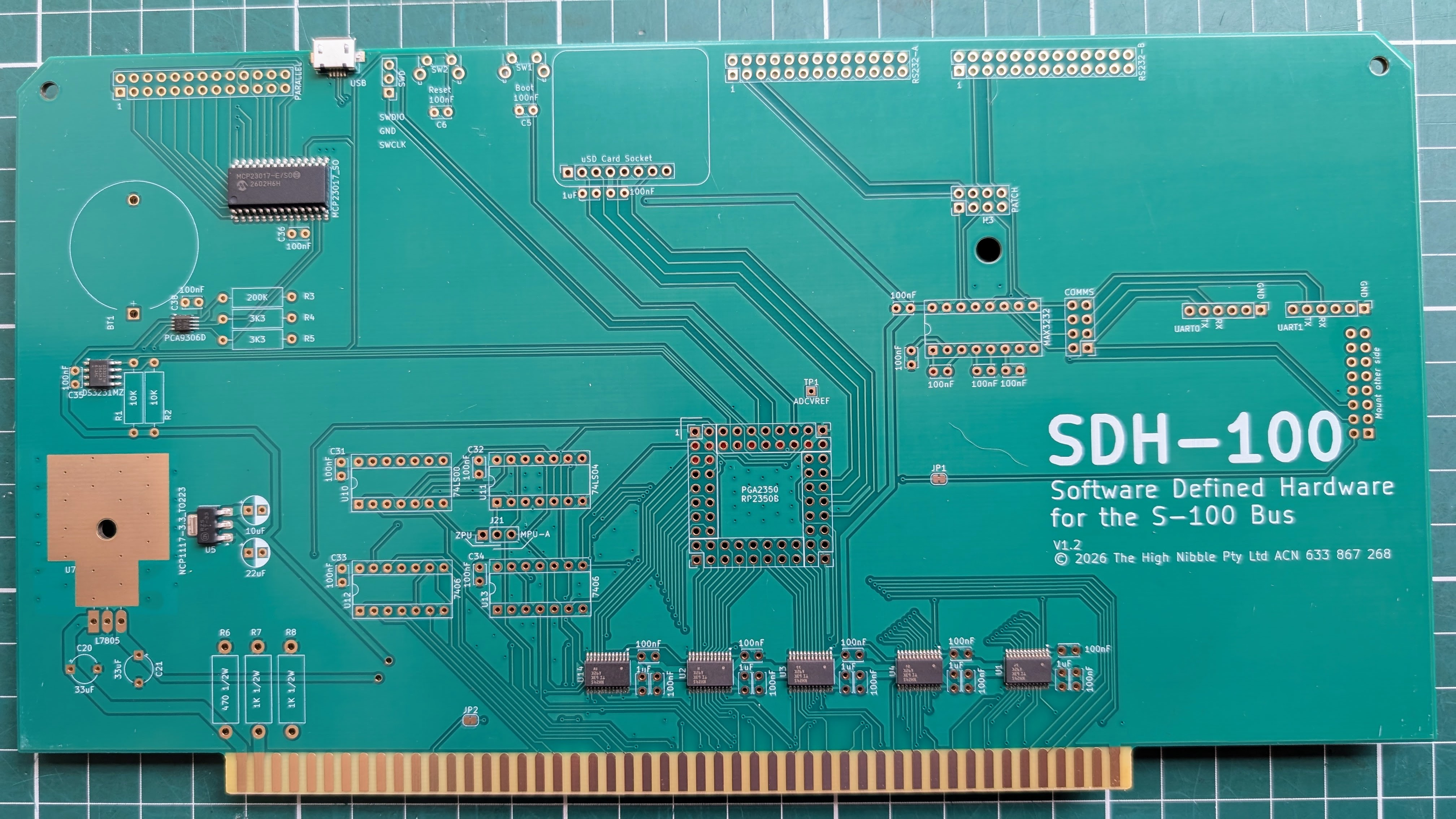
The following SMD parts come already assembled on the PCB as per the image below — no SMD soldering is required during kit build. They are listed here for reference only.
| Qty | Part | Footprint | Refs |
|---|---|---|---|
| 5 | SN74LVC8T245 (level translator) | TSSOP-24, 0.65 mm pitch | U1, U2, U3, U4, U14 |
| 1 | NCP1117-3.3 (regulator) | SOT-223-3 | U5 |
| 1 | DS3231MZ (RTC) | SOIC-8, 1.27 mm pitch | U15 |
| 1 | PCA9306D (level translator) | SSOP-8, 0.65 mm pitch | U16 |
| 1 | MCP23017 (I/O expander) | SOIC-28W, 1.27 mm pitch | U17 |
| 1 | USB Micro-B socket (Amphenol 10104110) | SMD signal pins + through-hole shield tabs | J10 |
# TTL UART connectors J12 & J13 (for FTDI etc...)
The supplied TTL UART connectors are right-angled and the PCB has been laid out with room for a typical FTDI (USB <-> serial) adapter to sit within the boundary of the SDH-100 PCB.
TIP
It is recommended that you solder these right-angled 6 pin headers in place while fitted to your preferred FTDI adapter to correctly align the positioning of the adapter.
In my case I found that the right-angled 6 pin headers needed to sit higher in the through-holes and not sit flush to the PCB to achieve this.
# Optional bleed resistors (R6, R7, R8) - not supplied
R6, R7, and R8 are optional 1/2 W bleed resistors. Install them only if your S-100 power supply does not already provide bleed resistors of its own — they help dissipate any residual charge held in the power-supply capacitors after the supply is switched off.
# Interactive Bill of Materials
The interactive bill of materials lets you click components in the schematic to locate them on the PCB (and vice versa). It opens in a new tab.