# VT132 Bill of Materials
Note:
The BOM is yet to be updated to include details of
- the Stand Alone edition
- the USB interface for USB-HID keyboard support
The parts listed below are common for both editions with the exception of:
- the Through Hole (THT) headers supplied
- the Printed Circuit Board (PCB)
TIP
To see the images in full size you can right-click on an image and Open Image in New Tab
Notes on the PCB
- The silk screen on the Beta Kit PCBs (V1.3) is not final
- Part identifiers are correct and there are no known errors
- Graphic decals and label placement are not final
# Surface Mount Device (SMD) components
Don't Panic
- Yes there are two SMD components!
- You can do it!
- You can do it with a regular soldering iron, but you are going to need flux
| Part | Quantity | PCB | Description |
|---|---|---|---|
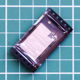 | 1 | ESP32-WROVER U1 | ESP-32 WROVER Module |
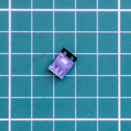 | 1 | NCP1117-33 U2 | NCP1117-33 LDO Linear Regulator |
# Through Hole (THT) components
| Part | Quantity | PCB | Description |
|---|---|---|---|
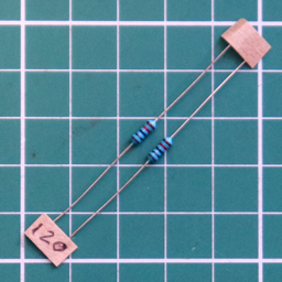 | 2 | R1, R2 | 120 Ohm Resistor [Brown, Red, Black, Black, Gold] |
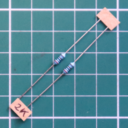 | 2 | R3, R4 | 2K Ohm Resistor [Red, Black, Black, Brown, Gold] |
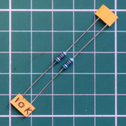 | 1 | R5 Vertical | 10K Ohm Resistor [Brown, Black, Black, Red, Gold] |
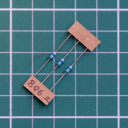 | 3 | R6, R8, R10 | 806 Ohm Resistor [Grey, Black, Blue, Black, Gold] |
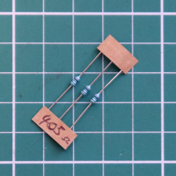 | 3 | R7, R9, R11 | 405 Ohm Resistor [Yellow, Black, Green, Black, Gold] |
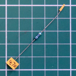 | 1 | R12 | 4.7K Ohm Resistor [Yellow, Purple, Black, Brown, Gold] |
| 1 | R13 | 10K Ohm Resistor [Brown, Black, Black, Red, Gold] |
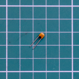 | 1 | C1 | 100 nF (104) MLC Capacitor |
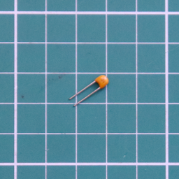 | 1 | C2 | 1 uF MLC (105) Capacitor |
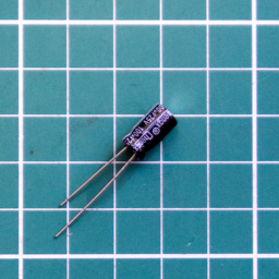 | 1 | C3 | 100 uF Electrolytic CapacitorElectrolytic capacitors have polarity, ie. they must be inserted the correct way around to function properly. |
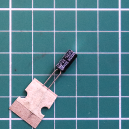 | 1 | C4 | 22 uF Electrolytic CapacitorElectrolytic capacitors have polarity, ie. they must be inserted the correct way around to function properly. |
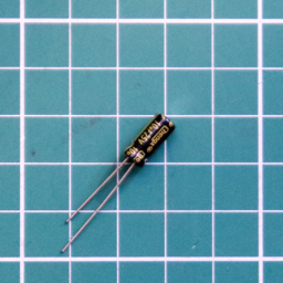 | 1 | C5 | 10 uF Electrolytic CapacitorElectrolytic capacitors have polarity, ie. they must be inserted the correct way around to function properly. |
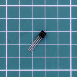 | 1 | Q1 | S8050 NPN Transistor TO-92 |
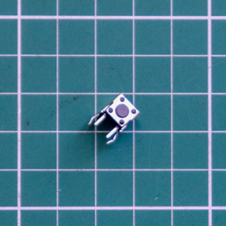 | 2 | Prog, Reset | Tactile Push Button Switch SPST - Right Angled |
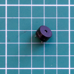 | 1 | Bell | Buzzer 12.2mm dia.The Buzzer is polarized, ie. it must be inserted the correct way around to function. +VE to the Square Pad |
# Through Hole (THT) headers
| Part | Quantity | PCB | Description |
|---|---|---|---|
 | 2 | JP5, JP6 5V Pwr | 2 Pin Header - Horizontal |
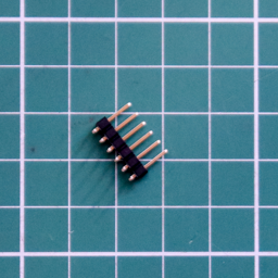 | 2 | FTDI Program, Modem Port B | 6 Pin Header - Horizontal |
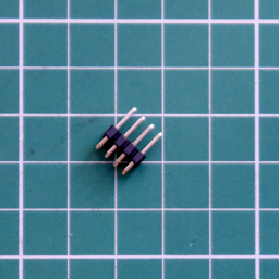 | 1 | JP1 to JP4 RxA/TxA RxB/TxB | 8 Pin Header (4x2)- Vertical |
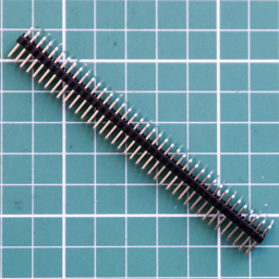 | 1 | Pin 1 | 80 Pin Header (40x2)- HorizontalRC2014 Pro Bus Connector. Remove the unneeded pins from the upper row. |
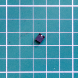 | 6 | For JP1 to JP6 as required | Header Pin ShuntsTo be placed only on JP1 to 4 for normal operation. |
# Through Hole (THT) connectors
| Part | Quantity | PCB | Description |
|---|---|---|---|
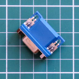 | 1 | VGA | DB15 VGA Female Socket - Right Angled |
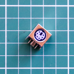 | 1 | Keyboard | Mini-DIN-6 PS/2 Keyboard Female Socket - Right Angled |
# Printed Circuit Board (PCB)
| Part | Quantity | Description |
|---|---|---|
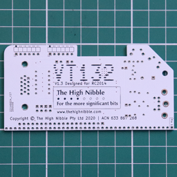 | 1* | Back view |
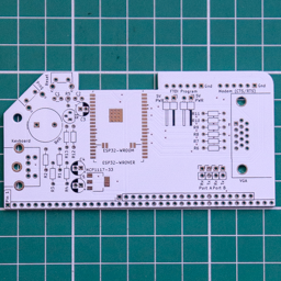 | 1* | Front view |