# Configuration
The S-132 requires only minimal configuration to get working.
The majority of features require no configuration to make work. However, the boot.conf file on the IMSAI8080 or Cromemco Z-1 replica must be edited to enable the TTY: (TTY2: & TTY3: - Cromemco Z-1 only) and VIO: keyboard (IMSAI8080 only) to be recognized as input/output devices by the HAL in the IMSAI8080 or the HAL in the Cromemco Z-1 respectively.
The VT100 terminal emulation (VT132), on the other hand, has extensive configuration options. See the VT132 Operation Manual for details.
# Start-up
With the S-132 connected to the IMSAI8080 or Cromemco Z-1 replica along with a VGA monitor and suitable keyboard, apply power and press the hardware reset on the IMSAI8080 or Cromemco Z-1 replica. As the replica boots it will force the S-132 to reboot.
The S-132 will perform a hand-shake with the ESP32-PICO-KIT on the replica and you will (may) briefly see the message
Host found
displayed in the upper left-hand corner of your VGA monitor. This will rapidly be replaced with the message
Wait
and a brief bell tone from the buzzer while the VT100 terminal initializes and retrieves its setting from the NVRAM.
TIP
When you first start the S-132, or after a full firmware re-flash (not an upgrade) it is completely normal to see the massage
Error
and a long bell tone from the buzzer.
This is the original behavior of the VT100 terminal and indicates that no settings were saved in NVRAM.
To avoid this message and warning tone in future simply go to one of the VT100 menus and save settings to NVRAM.
# Power Options
The S-132 can be powered from the connected IMSAI8080 or Cromemco Z-1 replica. Additional power is not required.
Alteratively, the S-132 can provide power to the connected IMSAI8080 or Cromemco Z-1 replica if you connect a DC power supply via the DC barrel jack on the S-132. In which case you should remove any USB cable providing power to the connected IMSAI8080 or Cromemco Z-1 replica.
When used with the SDH-100 the S-132 is powered from the +5VDC regulated by the SDH-100. Do not use the DC barrel jack to provide power in this configuration
# Configure the IMSAI8080 replica
You must edit the HAL settings in the boot.conf file.
You can use the Web Desktop, or mount the µSD card in a PC and edit the /imsai/conf/boot.conf file directly.
Enable and initialize the S-132
### Enable S-132
S132.init=1
To make the S-132 the first (and only) preference for the TTY: and VIO: devices, use:
### SIO-2 default port mappings (HAL)
SIO1.portA.device=S132TTY,WEBTTY,UART0
SIO1.portB.device=S132VIO,VIOKBD
To make the S-132 the first preference for the TTY: & VIO: devices and also simultaneously use the Web Desktop devices if connected, use:
### SIO-2 default port mappings (HAL)
SIO1.portA.device=S132TTY+,WEBTTY,UART0
SIO1.portB.device=S132VIO+,VIOKBD
To allow the Web Desktop to capture the TTY: and VIO: devices with priority ove the S-132, use:
### SIO-2 default port mappings (HAL)
SIO1.portA.device=WEBTTY,S132TTY,UART0
SIO1.portB.device=VIOKBD,S132VIO
For more information on the boot.conf see HAL configuration for the IMSAI8080
# Configure the Cromemco Z-1 replica
You must edit the HAL settings in the boot.conf file.
You can use the Web Desktop, or mount the µSD card in a PC and edit the /cromemco/conf/boot.conf file directly.
Enable and initialize the S-132
### Enable S-132
S132.init=1
To make the S-132 the first (and only) preference for the TTY: devices, use:
### TU-ART default device mappings (HAL)
TUART0.deviceA.device=S132TTY,WEBTTY,MODEM,UART0
TUART1.deviceA.device=S132TTY2,WEBTTY2,SCKTSRV1,UART1
TUART1.deviceB.device=S132TTY3,WEBTTY3,SCKTSRV2,UART2
To make the S-132 the first preference for the TTY: devices and also simultaneously use the Web Desktop devices if connected, use:
### TU-ART default device mappings (HAL)
TUART0.deviceA.device=S132TTY+,WEBTTY,MODEM,UART0
TUART1.deviceA.device=S132TTY2+,WEBTTY2,SCKTSRV1,UART1
TUART1.deviceB.device=S132TTY3+,WEBTTY3,SCKTSRV2,UART2
To allow the Web Desktop to capture the TTY: devices with priority ove the S-132, use:
### TU-ART default device mappings (HAL)
TUART0.deviceA.device=WEBTTY,S132TTY,MODEM,UART0
TUART1.deviceA.device=WEBTTY2,S132TTY2,SCKTSRV1,UART1
TUART1.deviceB.device=WEBTTY3,S132TTY3,SCKTSRV2,UART2
For more information on the boot.conf see HAL configuration for the Cromemco Z-1
# Configure the SDH-100
The S-132 is auto-detected at power-up by the SDH-100 when it is connected. No specific configuration is required on the SDH-100 to enable the S-132.
# TTY Display (VT100 emulation)
The TTY: display is the default. To return to the TTY: from other screens press Ctrl-Alt-F1.
The TTY: display is an advanced VT100 emulation with color, fonts, personalities and its own setup menu system. See the VT132 Operation Manual for more details.
# VIO Display
The IMSAI8080 VIO is an 80 × 24 character-cell display that emulates the
original 1979 video board. To bring the VIO onto the screen press
Ctrl-Alt-F4. To return to the TTY: press Ctrl-Alt-F1.
# Setup key — color and scan style
Each press of Setup (mapped to PrtScr / SysRq, or
Ctrl-Alt-Space on keyboards that lack PrtScr) advances the VIO through
six display states:
| Step | Phosphor colour | Scanlines |
|---|---|---|
| 1 | White | on |
| 2 | Green | on |
| 3 | Amber | on |
| 4 | White | off |
| 5 | Green | off |
| 6 | Amber | off |
The seventh press wraps back to step 1.
TIP
The current colour and scan style are part of the S-132 configuration that
Save Cfg writes to NVRAM, so once you have picked your preferred VIO look
it will come back the same way after a power-cycle.
# Dazzler Display
The Cromemco Dazzler is a low-resolution color graphics card. To bring the
Dazzler onto the screen press Ctrl-Alt-F5. To return to the TTY: press
Ctrl-Alt-F1.

While the Dazzler is the active device any printable keystroke is forwarded to the last-active console — typically the TTY: (or the VIO: if VIO: was the last console you used). This means you can flip to the Dazzler for graphics output and still type into the underlying program without flipping back. The Setup and PgUp keys are intercepted by the S-132 and used to change the Dazzler's appearance.
# Setup key — raster size
Each press of Setup steps the raster size down by 128 pixels and wraps:
| Step | Raster |
|---|---|
| 1 | 512 × 384 (default) |
| 2 | 384 × 384 |
| 3 | 256 × 256 |
| 4 | 128 × 128 |
Smaller rasters are centred on the screen with a black border, and pixels are drawn at proportionally larger sizes — useful if you want a punchier, more "chunky" Dazzler look.
# PgUp key — colour palette
In color mode (the Dazzler's normal mode of operation), each press of PgUp cycles between two palettes:
- Standard — the historically-correct 16-colour palette.
- Alternate — identical to Standard except Dark Yellow is replaced
with Orange (
255, 128, 0).
In monochrome (grey) mode the PgUp key has no effect — the grey palette is unchanged.
TIP
The raster size and the selected colour palette are both saved by Save Cfg.
# System Menu
The System Menu SYS: provides functions to inspect the host, mount and eject disk images, drive the IMSAI / Z-1 front
panel, configure the D+7AIO, save and restore configuration, and flash
firmware. It runs entirely on the S-132 — it does not need the host to be
running.
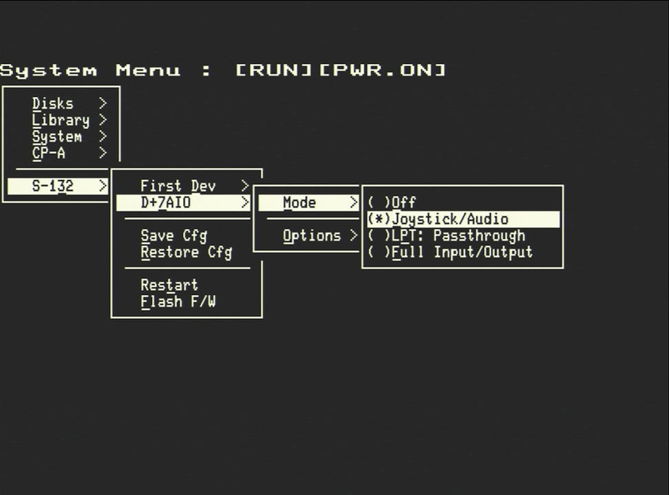
![System Menu — IMSAI8080 with [RUN][PWR.ON] in the title bar](/assets/img/system_menu.8a061346.png)
# Bringing up the System Menu
Press Ctrl-Alt-F6 to switch directly to the S-132 SYS: system menu.
To leave the menu, press Esc from the top level. The S-132 will return to
whichever device was active when you opened the menu.
# Navigating the menu
| Key | Action |
|---|---|
↑ / ↓ | move the highlight up / down |
Enter or Space | activate the highlighted entry |
Esc | go back one level (or leave the menu if at the top) |
Backspace | go back one level |
| underlined letter | jump to and activate that entry |
TIP
The highlighted entry's hot-letter is shown underlined in the menu — pressing that letter is faster than arrowing down to it.
# Title bar
The title bar of the System Menu shows what the host is doing:
| Host | Title format | Meaning |
|---|---|---|
| IMSAI8080 / Cromemco Z-1 | System Menu : [RUN][PWR.ON] etc. | run / wait state followed by power state |
| SDH-100 | System Menu : V1.0.0 [MPU-A] | host firmware version, then CPU type ([MPU-A] or [ZPU]) |
On the IMSAI / Z-1 you will see [RUN] when the CPU is running, [WAIT]
when the front-panel STOP is asserted, and nothing between the brackets
when the host is otherwise idle. [PWR.ON] and [PWR.OFF] reflect the
emulated front-panel power switch.
# Top-level structure
The menu reshapes itself to match the connected host. The layout below is for the IMSAI8080 / Cromemco Z-1; the SDH-100 layout is a subset (see the next section).
| Entry | What it does |
|---|---|
Disks > | mount and eject the four virtual floppy drives A:DSK:…D:DSK:. Each drive shows its currently mounted image, with Eject and a Mount > list of images on the SD card. |
Library > | the SD-card image library — all .dsk files at the top of the SD card, plus any >-prefixed remote images. |
System > | host-side inspection and configuration. See below. |
CP-A > | drives the emulated front panel — Run, Stop, Reset, Ext.Clr. Hidden on the SDH-100. |
S-132 > | configuration of the S-132 itself. See below. |
# System sub-menu
| Entry | What it does |
|---|---|
Guest | dumps the host emulator's guest-OS configuration (CP/M version, BIOS info, etc.) |
Host | dumps the host's own configuration — emulator version, sound mode, memory map |
Env | dumps the runtime environment string of the host |
Tasks | live snapshot of the host's RTOS task list — name, state, core, priority, stack high-water mark, CPU % |
Config > boot.conf | shows the contents of boot.conf from the host's SD card |
Config > system.conf | shows the contents of system.conf |
Reboot | reboots the host (not the S-132) |
# S-132 sub-menu
| Entry | What it does |
|---|---|
First Dev > | radio group choosing which device is brought up at S-132 power-on — TTY, VIO, or Dazzler. |
D+7AIO > | the D+7AIO configuration menu (see the D+7AIO Settings page). |
Save Cfg | writes the full S-132 configuration to NVRAM — initial device, D+7AIO settings, Dazzler raster size, Dazzler palette, VIO colour, VIO scan style. The terminal rings the bell on success. |
Restore Cfg | reads the saved configuration back from NVRAM. Useful if you have changed settings and want to revert without rebooting. |
Restart | restarts the S-132 only — the host keeps running. |
Flash F/W | starts the S-132 OTA firmware update flow over the host's network. |
TIP
Save Cfg saves only the S-132 settings. The VT100-terminal
settings (cursor style, keyboard layout, etc.) are saved separately by the
existing VT132 SETUP Save key.
# SDH-100 host — reduced layout
When the connected host reports itself as an SDH-100, the System Menu drops the entries that do not apply to that hardware and adds two SDH-100-specific inspection views:
| Entry | What it does |
|---|---|
Disks > / Library > | unchanged |
System > Memory Map | dumps the SDH-100 memory map provided by the host firmware |
System > Boot Log | dumps the SDH-100 boot log provided by the host firmware |
System > Env | unchanged |
System > Config > boot.conf | unchanged |
S-132 > | unchanged |
The Guest, Host, Tasks, system.conf, Reboot, and the CP-A
sub-menu are all hidden on the SDH-100. The title bar shows the SDH-100
firmware version and CPU type instead of the run / power indicator.
# D+7AIO Settings
The D+7AIO is configured entirely from the System Menu — there are no jumpers
or DIP switches on the board. Open SETUP with Ctrl-Alt-F6, then select
S-132 > D+7AIO >.
The menu adapts to the selected Mode: only the options relevant to the current mode are shown.
TIP
All ten D+7AIO settings are included in the
configuration that Save Cfg writes to NVRAM, so once you have the board
configured for your application you do not need to re-set it after a restart.
# Mode
The Mode selector controls how the D+7AIO behaves and which secondary options are presented.
| Mode | Use this when… |
|---|---|
Off | the D+7AIO is not fitted, or you want to disable it for this session |
Joystick/Audio | you have a pair of Cromemco-compatible joysticks (4 buttons + X/Y per stick) and/or want audio output via the two DAC channels |
LPT: Passthrough | the digital ports are wired to a Centronics-style parallel printer and you want the host to drive it directly |
Full Input/Output | you are running an application that uses the full seven analog inputs, two analog outputs, eight digital inputs and eight digital outputs of the D+7A interface |
When you switch Mode the menu resets the Options for the new mode to their recommended defaults (see below). This means it is safe to flip back and forth between modes while you are getting started.
# Joystick/Audio mode
The defaults applied when you pick Joystick/Audio are tuned for a pair of
Cromemco-style joysticks. You should not normally need to change them.
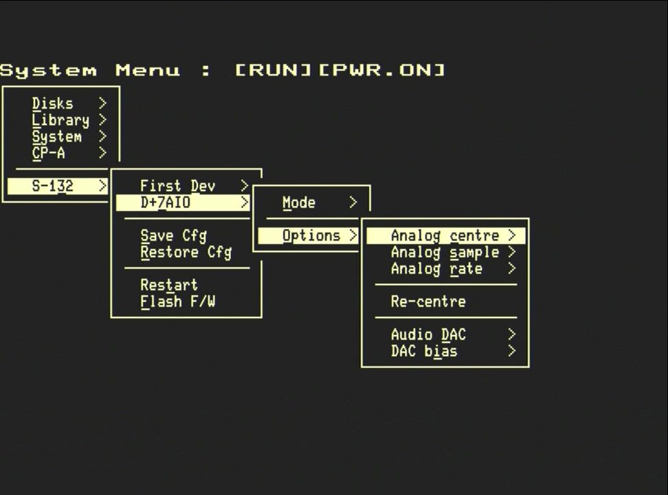
| Option | Default | Notes |
|---|---|---|
Analog centre | Zeroed | report joystick position relative to the stored centre. Use Raw to send the unmodified ADC reading instead. |
Analog sample | Average 4 | 4-sample running average smooths out ADC noise on cheap potentiometers. Raw reports each sample as it is read. |
Analog rate | 60 Hz | how often the joystick is polled. 30 Hz is plenty for most games; 1 KHz is only useful for Full Input/Output mode. |
Re-centre | — | resamples the four joystick axes 32 times and stores the average as the new centre position. Use this if a joystick is showing a non-zero rest position. |
Audio DAC | Split | how the host's two audio channels are routed to the ESP32's two DAC outputs. See below. |
DAC bias | Signed | how the host's 8-bit audio sample is decoded. See below. |
The Audio DAC option controls routing of the two audio channels sent by the
host:
- Split — host channel A1 → DAC 1, host channel A3 → DAC 2 (stereo, the Cromemco JS-1 convention)
- Mix to A — both host channels are sent to DAC 1
- Mix to B — both host channels are sent to DAC 2
The DAC bias setting must match the encoding used by the host's audio
routine. Signed treats the byte as −128…+127 around silence; Unsigned
treats it as 0…255 with 128 as silence. If audio sounds clipped at the loud
parts and silent in the middle, you have the wrong bias selected — flip it.
Once configured, a Re-centre is performed automatically the first time the joystick is polled. The joystick will continue to report data even when the D+7AIO screen is not the currently displayed device — the screen is only the inspector, not the gating.
# LPT: Pass-through mode
LPT: Passthrough has no further options — the eight digital outputs and the
STB output strobe are wired up as a Centronics-style parallel port, and the
two digital input bits _ACK and BUSY are read back for handshake.
When the host sends a byte to the D+7AIO it is buffered on the S-132. The
S-132 forwards each byte to the printer when the printer asserts _ACK high
and BUSY low. If the host outruns the printer, the S-132 sends back an
in-band flow-control on the D+7AIO channel.
TIP
Pass-through requires nothing else on the D+7AIO connector beyond the printer cable adapter. The board's analog inputs and outputs are unused in this mode.
# Full Input/Output mode
This mode exposes the full D+7AIO peripheral set to the host: seven 8-bit analog inputs (via the on-board MCP3008), two 8-bit analog outputs (via the ESP32's DACs), eight digital input bits and eight digital output bits with an output strobe.
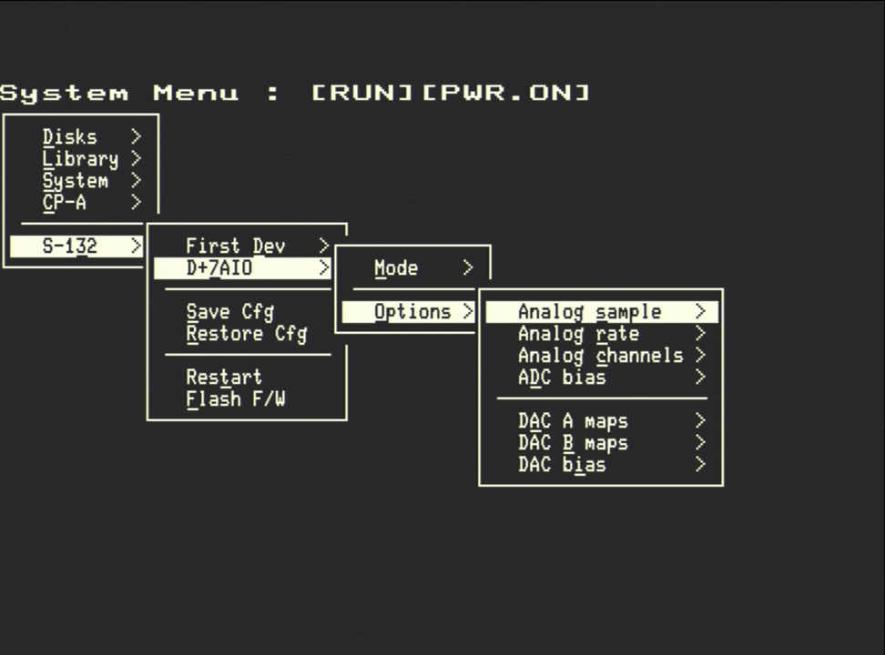
Defaults when you pick Full Input/Output:
| Option | Default | Notes |
|---|---|---|
Analog sample | Raw | no averaging — every poll sends the raw ADC value |
Analog rate | 1 KHz | the fastest the polling task will run |
Analog channels | ..A7 | poll all seven analog inputs each cycle. Pick a lower channel to stop the S-132 reading channels you are not using — A1 only polls only A1, ..A4 polls A1 through A4, and so on. |
ADC bias | Signed | how the 8-bit sample is sent to the host. Signed = −128…+127 (mid-rail = 0); Unsigned = 0…255 (mid-rail = 128). |
DAC A maps | A1 | which host analog output channel drives the ESP32's first DAC |
DAC B maps | A3 | which host analog output channel drives the ESP32's second DAC. The DAC outputs are not on adjacent host channels by default to match the JS-1 convention. |
DAC bias | Signed | how the 8-bit DAC sample from the host is interpreted before it reaches the DAC |
Only the analog input channels that are enabled by Analog channels are
forwarded to the host — the others are ignored. This is cheaper than reading
all seven channels and discarding the unused ones.
The two DAC A maps and DAC B maps lists let the host's analog-output
namespace be mapped onto the S-132's two physical DACs in any combination. If
the same channel is selected for both, both DACs are driven by that channel
(the on-screen indicator shows >+ next to the channel).
The Analog centre and Re-centre controls are not shown in this mode —
analog input is always reported as the raw ADC reading. If your application
needs centring around a zero point, do it on the host side.
# ADC and DAC bias — choosing Signed or Unsigned
The ADC bias and DAC bias settings select how the 8-bit byte that travels
between the host and the D+7AIO is interpreted:
- Signed — the byte is a two's-complement signed value, −128…+127. A value of 0 is mid-rail; a negative value is below it.
- Unsigned — the byte is an unsigned value, 0…255. A value of 128 is mid-rail; 0 is the lowest reading.
Pick the bias that matches what the program running on the host expects to read or write. If you do not know, Signed is the historically common choice for Cromemco software and is the default. The two settings are independent — you can run signed-mode input alongside unsigned-mode output if that is what the application wants.
# Saving the configuration
D+7AIO settings persist only after you select S-132 > Save Cfg. Restart or
power-cycle without saving and the board will come back up with the
compile-time defaults (Mode = Off).
Restore Cfg re-reads the saved state. There is no factory-reset entry — to
go back to first-power-on defaults, do a Save Cfg while Mode is Off and
the other options are at their out-of-box values.
# D+7AIO Display
To bring the D+7AIO display onto the screen, press Ctrl-Alt-F7. The display
only opens when Mode is Joystick/Audio or Full Input/Output — in Off and
LPT: Passthrough mode the hot-key is ignored.
TIP
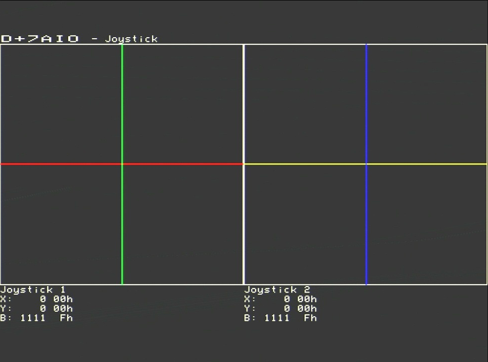
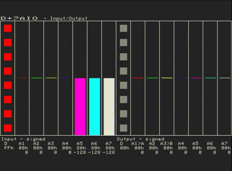
The D+7AIO display has two panes: a Joystick view (two crosshair
panels showing X / Y / buttons) and an Input/Output view (seven analog
bars + eight digital bits, both directions). Press J while the display is
active to swap between them. Press Z to toggle the zero-line basis.