# VT132 Operation Manual
# Assembly
TIP
If you are unsure, or unfamiliar with soldering the Surface Mount Device SMD components, there is an excellent series of five (5) videos on YouTube produced by The ShadowTron Blog that walk you through the assembly and soldering of the VT132.
TIP
The large, square ground pad under the ESP32 module does NOT need to be soldered. This is simply a feature of the default PCB footprint for ESP32 modules but is not needed for electrical ground (GND). That is provided by a number of other pins on the ESP32 module (1, 15 & 38).
It can provide additional thermal relief for the ESP32 module but this is generally not required. The pad can be soldered if using SMT reflow soldering techniques eg. solder paste and a reflow oven.
TIP
The production VT132 comes pre-flashed with a working firmware image. Firmware updates are published on the GitHub repository along with instructions on how to flash new firmware.
# VT132 Designed for RC2104 edition
It is assumed you have already successfully assembled a working RC2014 and know what you are doing in this respect. The silkscreen on the PCB along with the details provided in the VT132 Bill-of-Materials should provide sufficient information to assemble a working VT132.
Locating the VT132 in the RC2014 backplane
It was noted during the Beta testing that owing to the height of the PS/2 keyboard connector, some thought must be given to which slot in the RC2014 backplane you place the VT132.
Slot 1 in the Backplane Pro is always a good choice but you may need to add the extra 20 pin female header to the backplane for this slot to pick up the bus pins for the PortB UART.
Some suggested adding electrical insulation tape over the PS/2 connector shell to insulate it from an adjacent PCB.
# VT132 Stand Alone edition
It is assumed you have already successfully assembled a working system and know what you are doing in this respect. The silkscreen on the PCB along with the details provided in the VT132 Bill-of-Materials should provide sufficient information to assemble a working VT132.
A number of components are optional on the VT132 Stand Alone edition as follows:
- DC barrel jack
- only required if you plan to power your VT132 from a power source with a 2.0mm - 2.1mm DC barrel jack (center pin +VE)
- LM7805 linear power regulator and accompanying capacitors (10µF and 100µF electrolytic)
- only required if you want to power the VT132 from a DC voltage source other then +5VDC ie. +8VDC to +12VDC
- MAX3232 ICs & sockets and accompanying capacitors (5 x 100nF ceramic, per MAX3232)
- only required if you want RS-232/EIA level serial communications over the DTE and DCE connectors
- not required if you only want TTL level serial communications over the 6-pin straight headers
- DB25 (F) DTE, DE9 (M) DTE connectors for the terminal
- you need only install one or both of these connectors as required for your setup
- DB25 (M) DCE, DE9 (F) DCE connectors for the modem
- you need only install one or both of these connectors as required for your setup
# New: USB daughter board (Red PCB) for USB-HID keyboards
WARNING
If you are building the VT132 with USB keyboard support DO NOT install the:
- PS/2 keyboard connector
2 x 120 ohmand2 x 2K ohmresistors immediately behind the PS/2 keyboard connector footprint
The USB daughter board (Red PCB) for the USB keyboard interface is supplied with the surface mount (SMT) components already soldered in place. You need to solder on the:
- USB Type-A connector
- 6-pin male header, for connecting the USB daughter board (Red PCB) to the main VT132 PCB (White: RC2014, Black: Stand Alone)
I recommend you watch the YouTube video on assembling and attaching the USB interface for the best results.
# Hardware configuration
NVR (Non-volatile RAM) is not initialized on a new VT132
- At power-on or reset, following the 'Wait' message, a new VT132 will display 'Error' along with a series of bells
- This is expected because the NVR has not been initialized
- Once you write settings to the NVR (see Setup Screens) this error should not persist
Hardware reset
- The hardware 'Reset' press button on the PCB reboots the ESP32 (EN line reset)
- This will cause both the VT100 terminal and the modem to reset
- and will lose any unsaved settings on both devices
TIP
- The hardware 'Prog' press button has two functions:
- if flashing firmware to the ESP32 module over the FTDI connector this button grounds the 'BOOT' line (pin 25) for programming
- in normal operation pressing this button changes the baud rate of the modem
- each press cycles to the next supported serial baud rate of the modem (4800, 9600, 14400, 19200, 38400, 57600, 1152000)
- the selected speed is echoed in a message to the modem UART eg.
BAUD 19200 - you should keep pressing the button until you see the desired baud rate displayed
- the selected speed is stored in NVRAM and persists through resets and power cycling
# VT132 Designed for RC2104 edition
There is minimal hardware configuration that needs to be performed on the VT132
For normal operation on the RC2014 Pro bus (or similar) both the Port A and Port B UARTS from an existing serial card (RC2014 Dual Serial, or similar) should be enabled by placing shunts on the 4 jumpers JP1 to JP4 (RxA/TxA and RxB/TxB)
The FTDI Program 6-pin header on the top of the PCB is not connected to Port A on the RC2014 Pro bus. It is connected to a separate UART on the ESP32 and is only used for
- updating/re-flashing the firmware on the ESP32
- monitoring debug logs from the ESP32
- future expansion
The Modem Port B 6-pin header on the top of the PCB is connected to Port B Rx/Tx lines on the RC2014 Pro bus. In addition it:
- provides RTS/CTS flow-control lines, when enabled for the modem
- is designed to be compatible with serial cards such as the SC104 Z80 SIO/2 Module or similar
If you want to provide power to, or take power from either of the 6 pin headers then JP5 and JP6 will provide power or isolate the Vcc pin in the FTDI Program and Modem Port B 6-pin headers respectively.
WARNING
You should normally only connect one power source to the system at a time.
# VT132 Stand Alone edition
There are significantly more hardware configuration options on the VT132 Stand Alone edition. As noted above you need only install a number of optional components as required for your setup. All the optional components can be installed together if you want the maximum flexibility.
# Power configuration
There are six (6) different 2-pin, horizontal headers on the PCB for selecting power options.
WARNING
In most configurations only one (1) of these jumpers should be in place. Only connect more than one (1) if you have consulted the schematic diagram and made an informed decision to configure power in a specific configuration.
If you use JP6 to bypass the LM7805 5VDC linear power regulator, it is your responsibility to ensure you are providing regulated +5VDC to the VT132.
JP6(5V Select) bypasses the LM7805 5VDC linear power regulator and should only be put in place if you are supplying regulated +5VDC to the VT132 via the DC Barrel Jack or one of the EIA serial connectors for the modem (DCE) or the terminal (DTE)JP5(FTDI Power Vcc) allows +5VDC power to be taken (or given) over the 6-pin FTDI Program headerJP4(5V Vcc) allows +5VDC power to be taken (or given) over the 6-pin Modem TTL headerJP3(5V Vcc) allows +5VDC power to be taken (or given) over the 6-pin Terminal TTL headerJP2(+VDC) allows unregulated power to be taken (or given) over the 3x2-pin DCE - EIA Modem header or the Modem DB25/DE9 RS-232 serial connectorsJP1(+VDC) allows unregulated power to be taken (or given) over the 3x2-pin DTE - EIA Terminal header or the Terminal DB25/DE9 RS-232 serial connectors
TIP
The supplied DC Barrel Jack and the PCB layout is configured for center-pin-positive.
For the DB25/DE9 RS-232 serial connectors, Pin 9 (normally reserved in the RS-232 standard) can be used for providing unregulated power to the VT132 and is passed through the LM7805 5VDC linear power regulator unless this is bypassed by JP6.
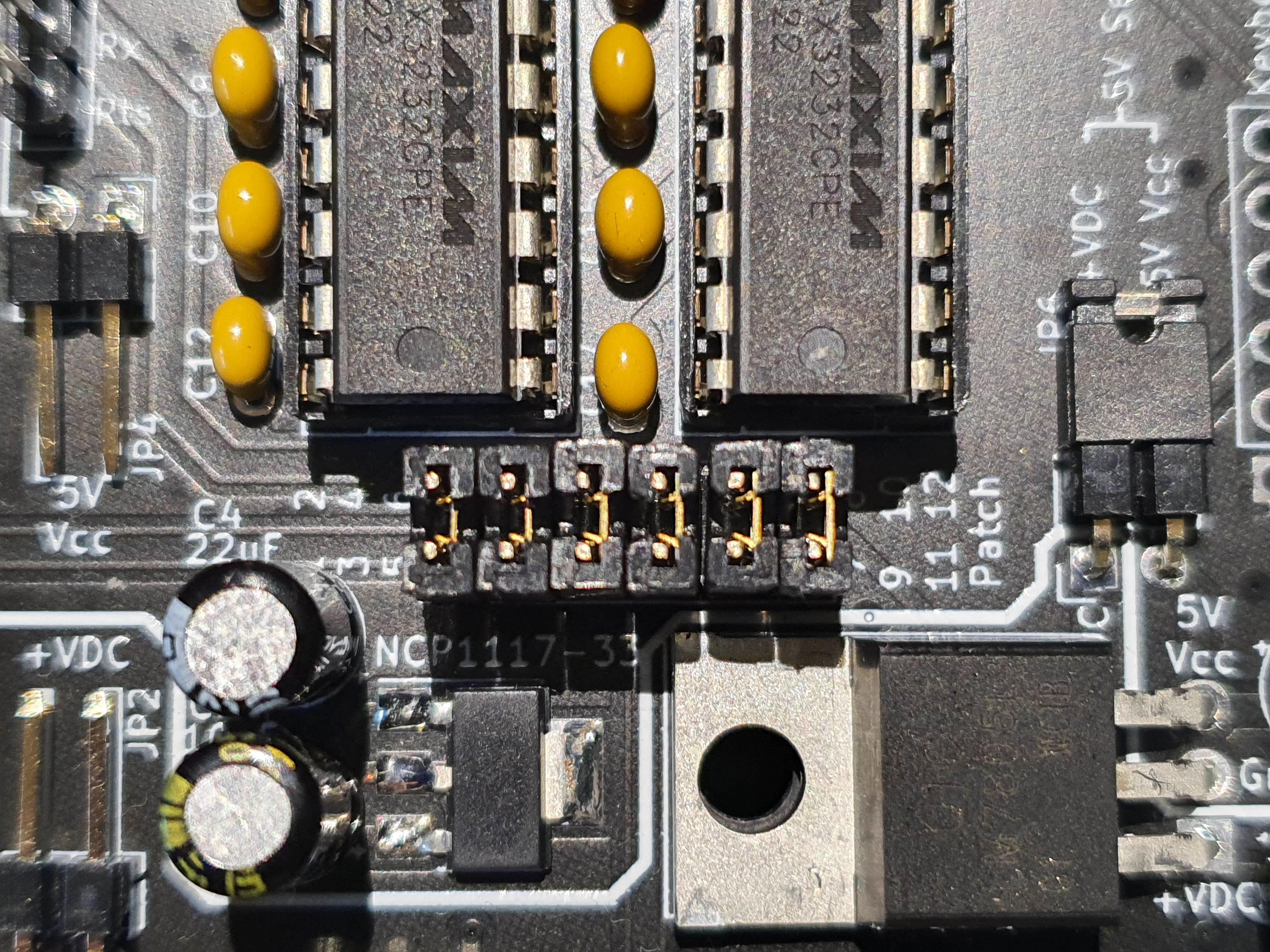
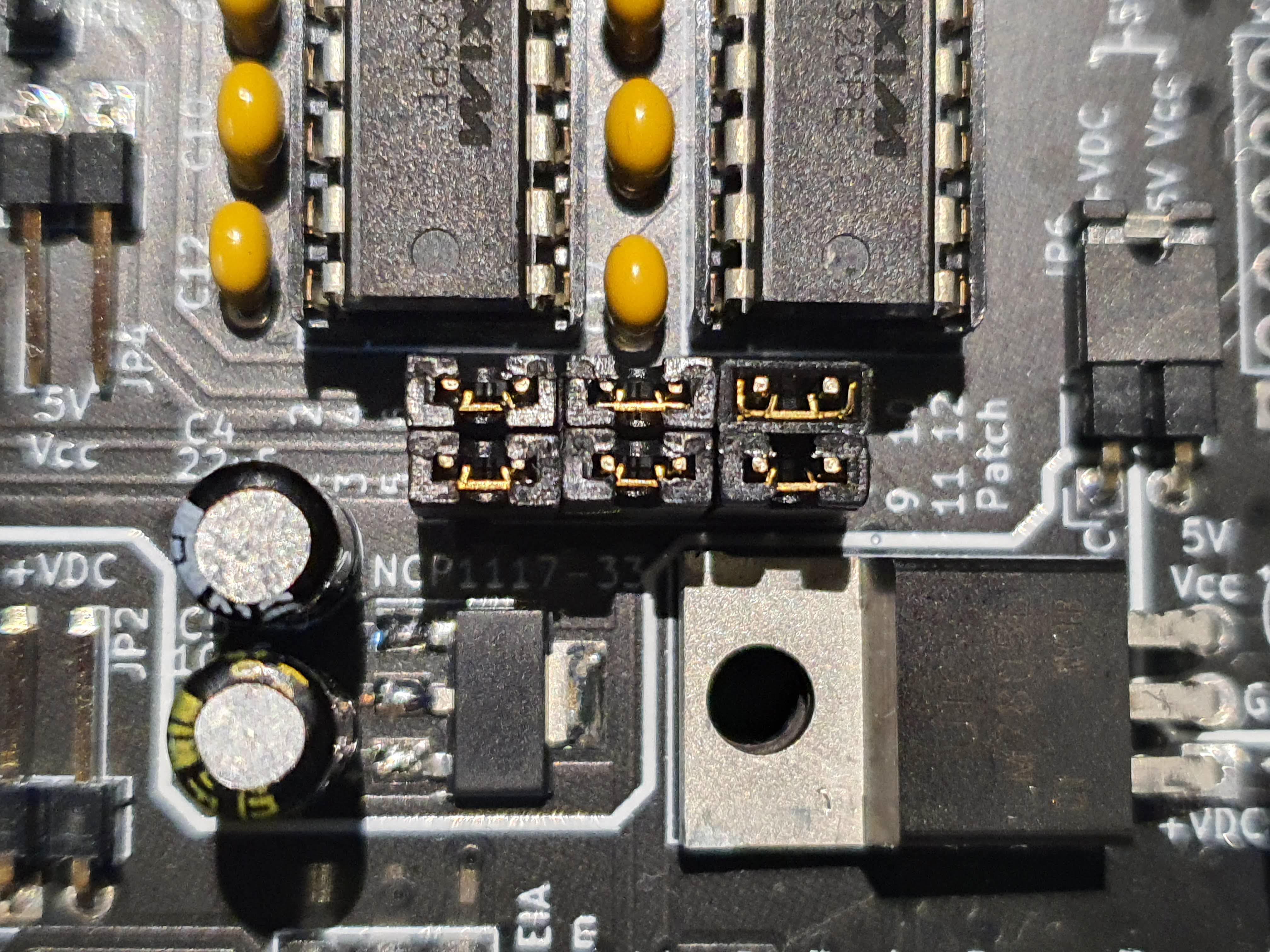
# Serial communications configuration
There is a 12-pin (6 x 2) header under the MAX3232 ICs labelled Patch that must be configured for pass-through &/or cross-over connection of each pair of RS-232/EIA signals by using shunts to jumper the pins in pairs as follows:
| Pins | Device | Signal | Mode |
|---|---|---|---|
| 1-2 | Terminal | Tx | straight-through |
| 3-4 | Terminal | Rx | straight-through |
| 1-3 | Terminal | Tx | cross-over |
| 2-4 | Terminal | Rx | cross-over |
| 5-6 | Modem | Tx | straight-through |
| 7-8 | Modem | Rx | straight-through |
| 5-7 | Modem | Tx | cross-over |
| 6-8 | Modem | Rx | cross-over |
| 9-10 | Modem | CTS | straight-through |
| 11-12 | Modem | RTS | straight-through |
| 9-11 | Modem | CTS | cross-over |
| 10-12 | Modem | RTS | cross-over |
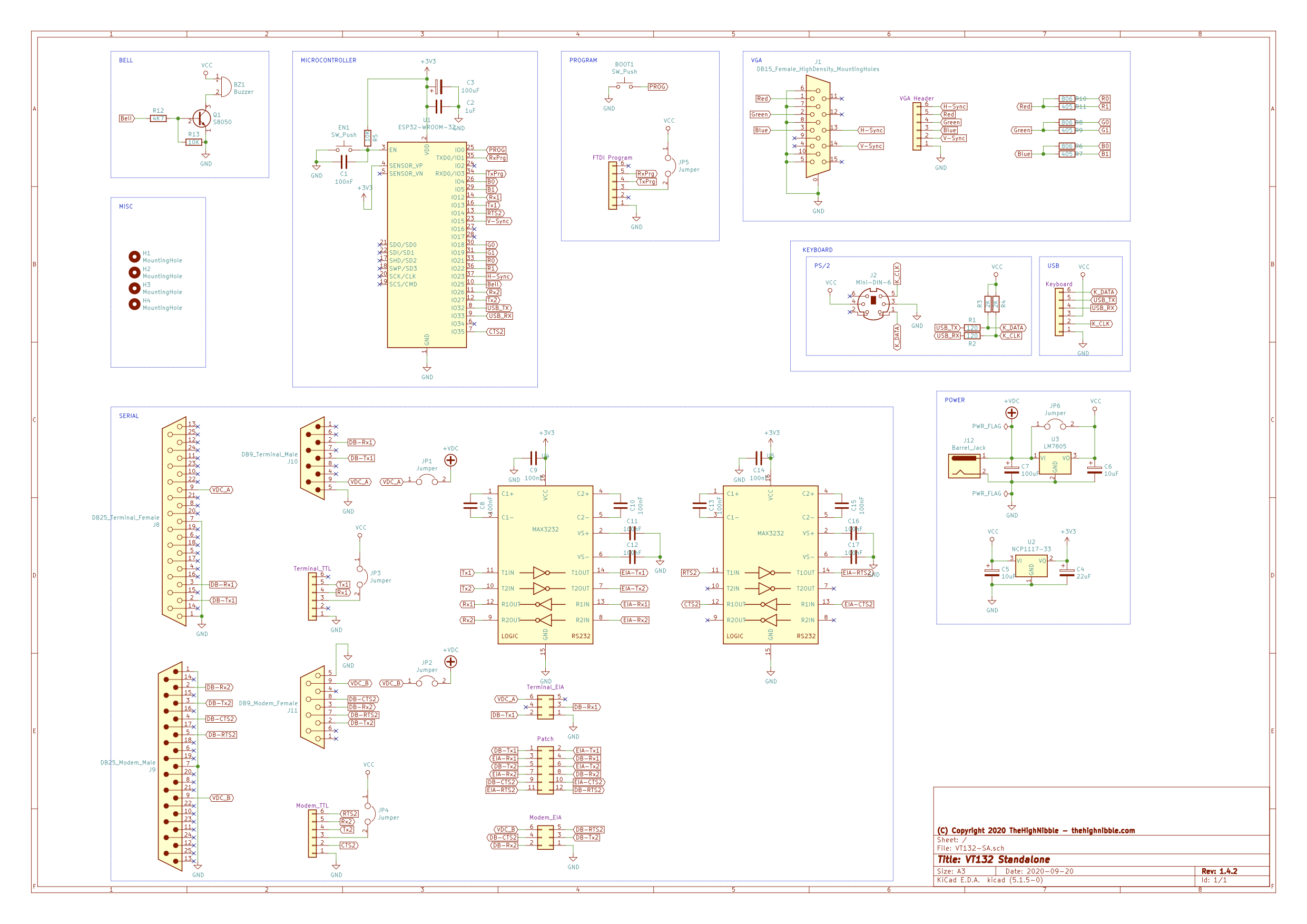
# VT132 Stand Alone schematic
# USB daughter board (Red PCB) for USB-HID keyboards
There is no additional hardware configuration required for the USB interface. The firmware will detect that the USB interface is installed and proceed to detect any attached USB-HID keyboard.
The USB interface is configured for plug-and-play ie. you should be able to unplug and reconnect a USB-HID keyboard while the VT132 is powered on, you can also change to a different keyboard.
WARNING
In rare circumstances the USB interface can lock-up and become unresponsive. In this case you may need to reset the VT132 with the Reset push button near the ESP32 or sometimes it will require you to power cycle the VT132.
# VT132 Quick Reference Guide Print-ready PDF
One of the VT132 Beta testers, ACN, prepared this print-ready, PDF, Quick Reference Guide for you. The site hosts the source in LaTeX and a copy of the published PDF file.
This is a living document and will be updated regularly as required.